|
|
Post by Dandy Dan on Jul 5, 2006 11:00:00 GMT -5
I talked to the bike shop that's doing my work again today. Here's their website (check out all the services they offer): www.cycleimprovements.com/Anyways, they said that there shouldn't be any problems with this piston because the sleeve is fully supported. They did say 1mm of sleeve left is the max you'd want to go but they said it should work out fine. They are planning to get to it tomorrow and I'll be picking it up on Saturday morning. I also asked them if it's going to be hard to get the rings in because stock the sleeve tapers outward at the very end to guide the rings in (picture a funnel). He said this taper would be reduced but they'd try and re-taper it a bit if there's room so it shouldn't be too hard. Also, he was amazed at how small the piston was...he said it's more like a shot glass than piston. He also commented that the clearance spec (gap between the piston and wall for the rings?) was very small but he thought it would okay since it's such a small engine. |
|
|
|
Post by chanito on Jul 5, 2006 19:03:01 GMT -5
 I am taking advantage of this guy while i can, anyway, i was going to do a how-to, but i will do it later, i have decided to post some pics of my progress, so this is the operatring table, it can be a picnic table and cover it with a fender cover, you need a clean working place 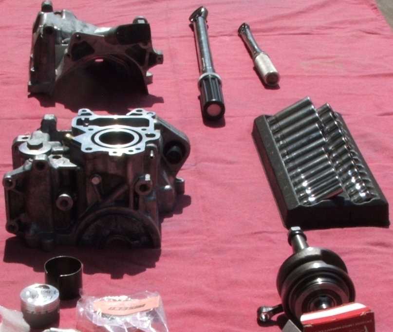 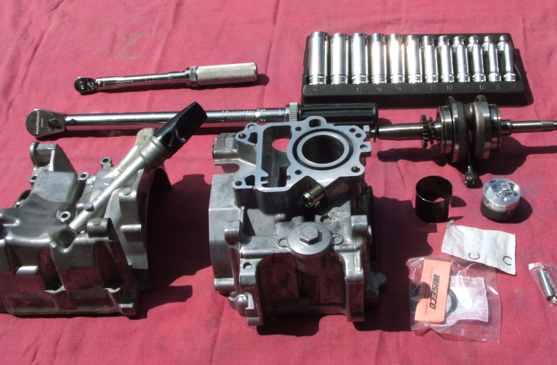 there is a need for lube and they should be handly 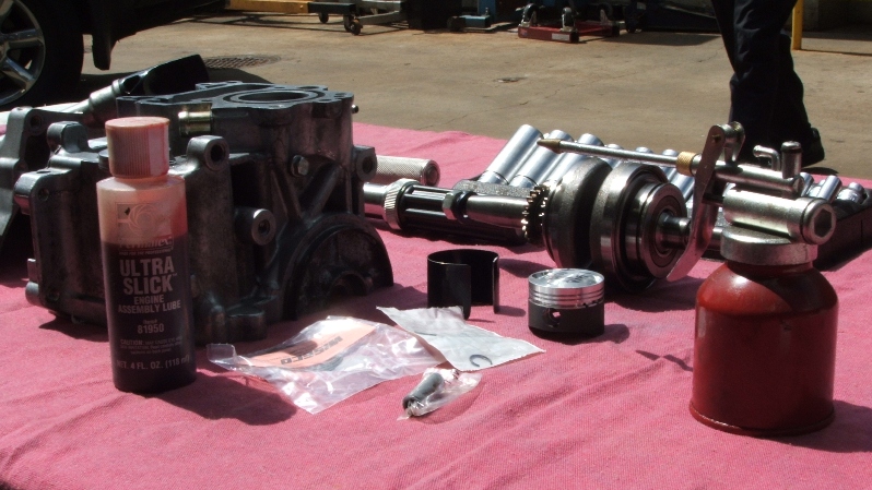 I realize that the boring have taken away the cone at the bottom of the cylinder that allows the ring to be compresed, i had to make a tool out of a band use to seal the boxes where engine come in, i might to make some more so i can send it with the kit upon request 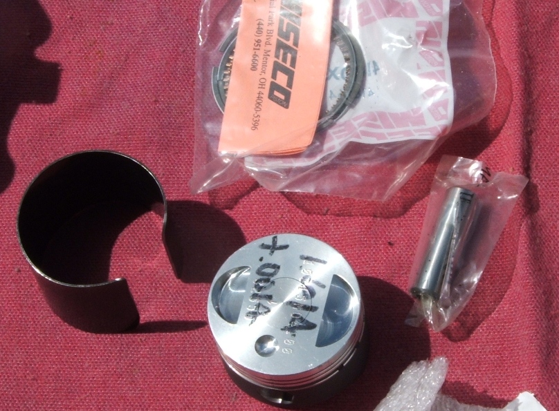 this is the motor with the piston in it 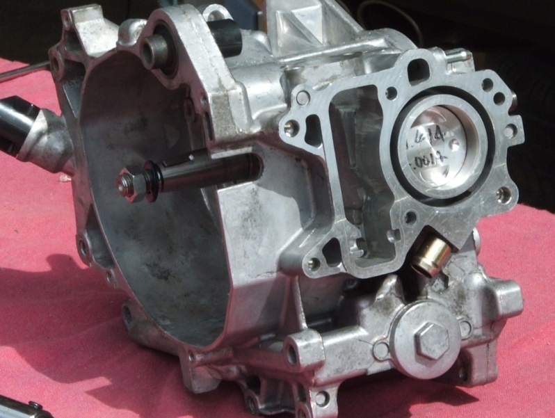 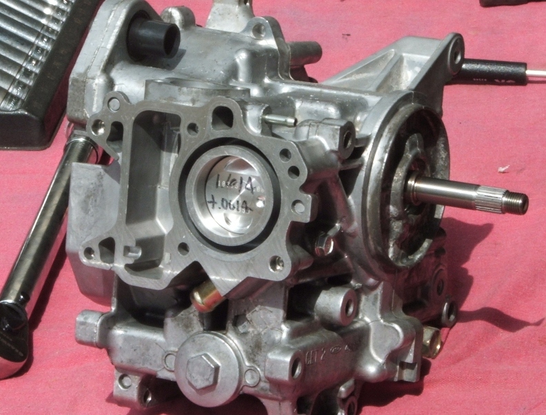 I hope to do some more tomorrow, hopefully i should finish, i will be on the site again later, so please let me have any feedback, and thanks to DD for remain me to figure out a way to compress those rings, probably a small engine shop might have the right tools, but i did not 
|
|
|
|
Post by chanito on Jul 5, 2006 20:13:36 GMT -5
 Here are a before and after (the before is from the BSS site  ) 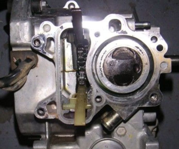 And this is Frankie with the big bore piston 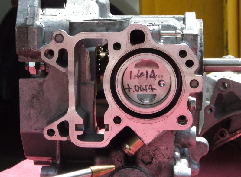
|
|
|
|
Post by Dandy Dan on Jul 6, 2006 9:09:22 GMT -5
Nice pics Chanito! Thanks for keeping us posted on your progress....now I know what to expect when I'm reacquanted the Lorax's engine on Saturday. I've got a couple more questions:
1 - Could you briefly comment on assembly lube. i.e. how much does it cost? Where do I use it? Did you dump it on your crankshaft bearings or use engine oil for that? I imagine you can get it at any motorcycle shop or autoparts store.
2 - What are those numbers written on your piston?
3 - Do you need to do your engine break in period over again since the walls have been re-honed?
Thanks for taking the lead in this. I really want to get my engine put all back together this saturday but I only have about 5 hours and I need to make at least 4 variator tools too which is gonna consume a lot of my time. Hopefully we can start to get some jetting info out there soon. I'm guessing we're gonna need to move to a 40 slow jet with a main around 90 but it's tough to say. You should really order some slow jets.
|
|
|
|
Post by chanito on Jul 7, 2006 22:31:09 GMT -5
 First to answer to DD questions 1.- I love to use the assembly lube, it works great and the little container usually last me for a couple of car engines, so it should last for a lot of ruckus engines, the cost is around 3 dollars per bottle, i usually coat everything that will get lube with engine oil, and use one of those brushes they use on plumbing for preparing the surfaces for soldering, also i use one of those plastic syringes for applying the silicone, as i find it give me better control, you can get them for cent at your local pharmacy, because i do not buy the expensive needles, i just squeeze the silicone from the tube into the syringe and then just use it to apply the bead of silicone to the surfaces being seal 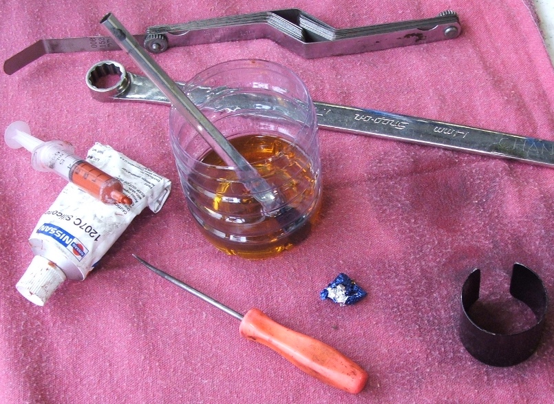 2.-the number were put in by the machine shop, they are just the diameter of the piston in inches and the require clearance 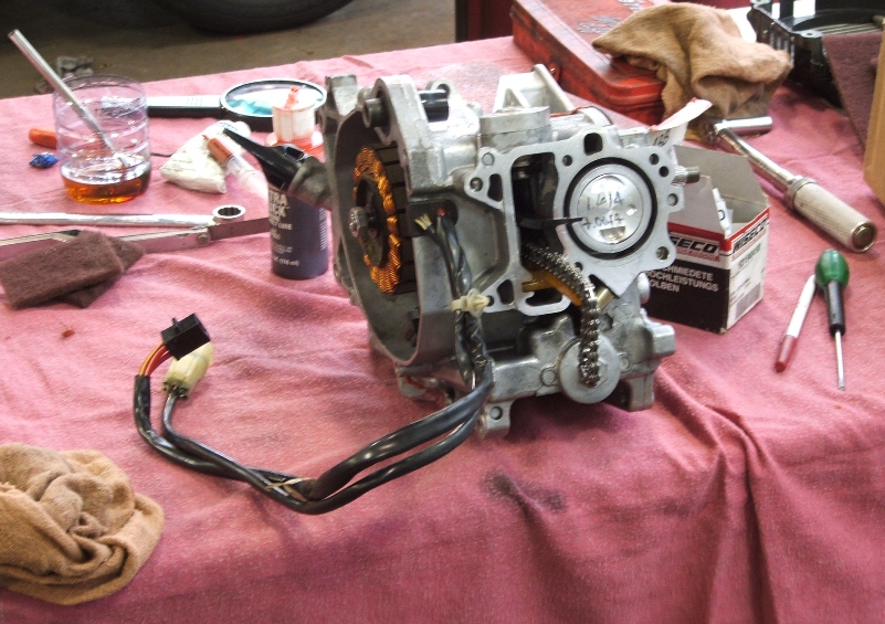 3.-And yes you will need to break in your engine after the piston install. I forgot to mention that i checked the ring gap and is was within specs, so my day went very smooth, do not forget to check it any way 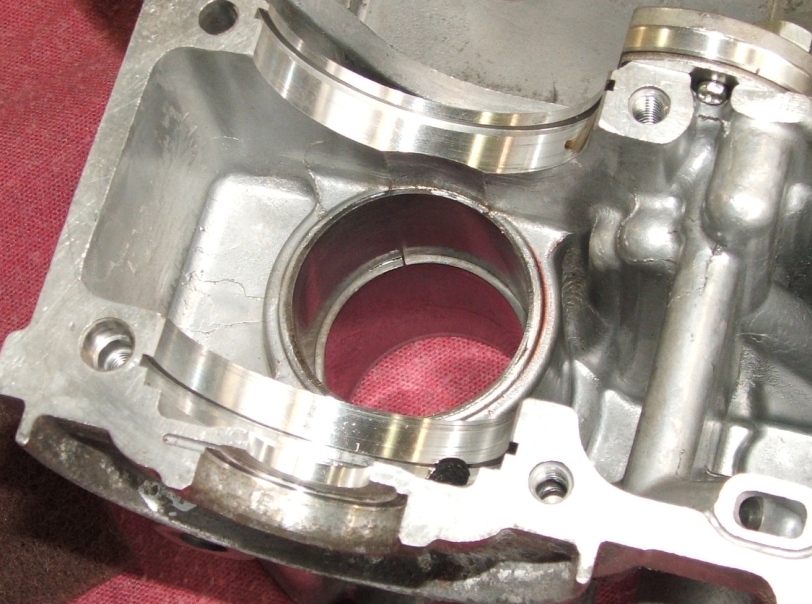 Also i used the bottom of a soda bottle to put some engine oil so i could coat the rings and piston properly 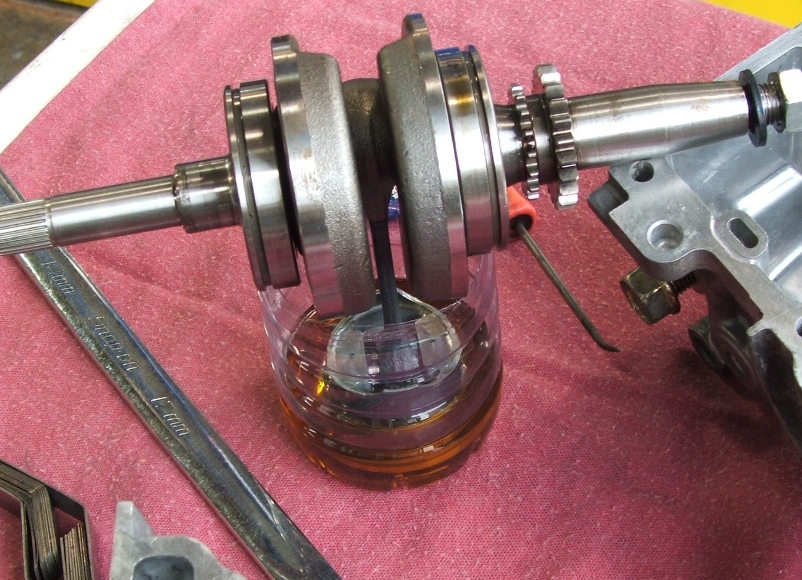 The tool proved to be a necessity as installing the piston with out it can not be done, a motorcycle shop should have a special tool, that will compress the rings so the piston can be installed, but i do not have one, so i make me one, if you are buying the kit and will do the work yourself, let me know i can provide one with the kit. the syringe give an even bead of silicone so the engine halves will seal properly 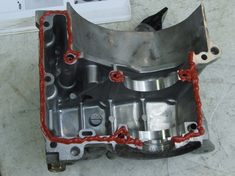 So far working during lunch and taking the pics and then clean and go back to work is harder than i though, i need a photographer to take the pics meanwhile i am assembling the engine, so i can work faster, but anyway, i am ready to mount the head next, i will post pics of that then 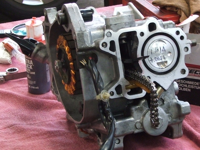  if you have any comment or question please let me know
|
|
|
|
Post by Kami no Chiizu on Jul 7, 2006 23:02:25 GMT -5
 I stole that one off ADVRider. I stole that one off ADVRider. |
|
|
|
Post by ZOOMER46 on Jul 8, 2006 15:12:29 GMT -5
chanito, do you have any torq settings that you can give,maybe at least
on the more major nuts and bolts?
and also,was your cam chain buffer worn?
and is it worth replacing at this stage anyway?
or does this thing EVER wear,cos no-one ever says it does ?
you mention about the piston ring compressor, but,if not
available,do you think it is a good idea to ,by free hand,
give a leed-on chamfer at the base of the liner?
is it better to re-fit the piston from top or bottom of the liner?
do you recommend greasing the gaskets at all?
nice piston btw. ;D
|
|
|
|
Post by chanito on Jul 9, 2006 8:24:53 GMT -5
This have become picture intensive, must be a killer on dial-ups, anyway there is some questions i need to answer, you should have your tech manual handy when doing engine work, most of the torque specs are in there, but there is a bunch of small 6mm bolts (they require a 10mm wrench) and you should torque them to 85 inch/pounds (they do not say so in the manual, but my experience tells me to do so) and torque ANY bolt that require you to tighten it. The cam chain guide were good so i did not need to change them, and this engine seems to have been use hard (i bought it used, so i do not know how it lived) so i think most engine will have them in good shape, but obviously check them when you take your engine apart. Is impossible to fit the piston from the top, so the only option is from the bottom, the engine comes from the factory with a funnel shaped cylinder and machining it for a bigger bore takes most of it out, the best solution would be to machine one back on, but i just had so hard a time finding someone boring my very small engine i do not think i could get that done, compressing the rings with your fingers would require smaller fingers than mine, and using tools like screwdrivers or pliers run the risk of scratching my expensive coating, maybe some plastic tools can do the trick, but i decided to make me a ring compressor out of some steel packing band and it worked like a champ. Do not grease you head gasket, it was design to seal by squeezing some ridges press into it, grease will get under the ridges preventing them from seating properly OK now back to the matter of the engine build up, i came to some facts while working on the head and i want to share them with you, first you can forget about a bigger carb as the limiting factor is the intake manifold 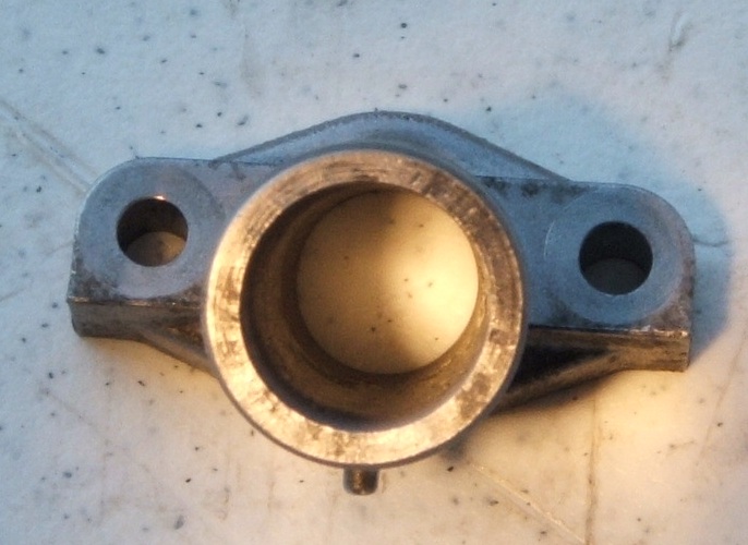 the side facing the carb is 19 millimeters but the side facing the head is just 16mm, because the intake is funnel shaped and sealed with an "0-ring increasing the size is impractical 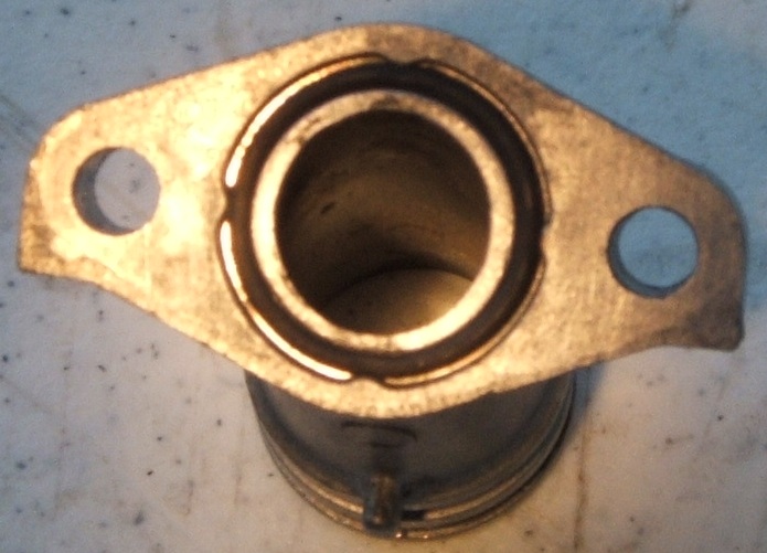 the head port itself is only 16mm so there is no need to increase the size of the intake anyway, unless you can invest on having the head extrude hone (a very expensive process, were they run an abrasive gel like substance thru the part, making it smoother and bigger), far more advance can be had by removing some stuff killing your flow 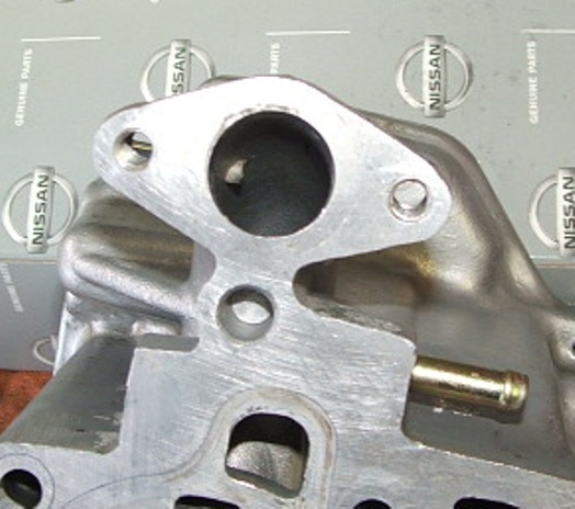 as you can see the vacuum port feeding the Pair valve goes into the intake track, getting rid of that intrusion will free some precious extra flow, so be careful with a small grinding and attack the little bugger  This photo shows some interesting facts, the intake track on our engines have to do a complete U-Turn in order to reach the cylinder, also you can see that the intake valve size matches the intake track size perfectly (the valve size is slightly bigger to compensate for the valve stem being on the way) so going for a bigger valve seems like more of a problem than a solution, nice to note how close to the combustion chamber the temperature sensor is, so the info going into the computer is very accurate (that is the threaded hole on the head between the intake port and the head) Having a straighter path for the intake would give far more benefits than any other head mod, but cutting the head and weld something to the head to fabricate a facing forward port is MAJOR SURGERY, so we have to be happy with what we got  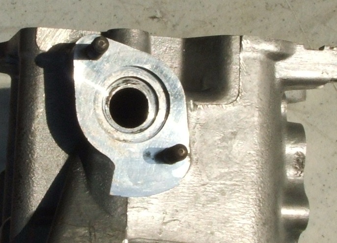 Here is what "i think" (that is so everybody know is just my opinion and not base in any proved fact) is the more potential for extra flow, as you can see the exhaust port is not perfectly centered in the head, some significant flow can be gained by centering the exit on the head, the way to do this is to get some machinist die or a permanent marker and paint or coat the port, then get a drill bit of a size that will put the point of the bit at the skinniest part of the flange and the wall of the bit against the side of the recess on the port and scribe a mark that will center the hole, and then go at it with you grinder and center the port ( this is confusing i might have to take some pics to illustrate this),  If you have questions please ask them so we can all figure out what else can be done ;D |
|
|
|
Post by tedsmini on Jul 9, 2006 17:45:27 GMT -5
Chano, is the extrude honing anything like we used to have that was called "vapor honing"? The pix were great, I used to use tin cans and worm drive hose clamps for ring compressors when I was poor and couldn't afford the proper tool. The only things I never scrimped on was anti-seize compound, rubber gloves and lots of the best assembly lube to keep everything clean and lubed. Learned this from the mech's at a famous racing garge in N.H. Caif named Fiasco Automotive. Only $30K in tools, tell the crew here how much a diagnostic machine costs and the monthly subscription for all the updates, recalls and service bulletins.  (when using anti-seize compound you need to be aware about the variance in torque readings  ) |
|
|
|
Post by Dandy Dan on Jul 10, 2006 9:00:22 GMT -5
Great pics Chanito! Lot of good information too....my only question is how do I check the 'ring gap? I imagine that's just the gap between the piston and the cylinder wall that's filed by the rings but to measure it seems hard because it's curved so a feeler gauge doesn't seem like it would fit well.
Anyways, the boring machine broke at the shop that was doing mine right before they got to my engine on Friday so my engine is still not done...that sucks but I probably wouldn't have had enough time to get it all back together on Saturday anyways. It's good that you are posting all these pics Chanito so I don't have to stop and do it so I can just keep chugging.
Anyways, I'll try and pick up some assembly lube this week...I couldn't find any at Canadian Tire but I'll try Parts Source or NAPA.
|
|
ZoomZoom
Ruckster
   '05 Ruckus, '97 Polaris 400L 4X4
Posts: 251
|
Post by ZoomZoom on Jul 10, 2006 19:20:51 GMT -5
Great pics Chanito! Lot of good information too....my only question is how do I check the 'ring gap? Maybe I can answer this one for chanito. Before sliding the rings unto the piston, just insert them in the head near where the piston would be on it's top stroke. Once you have the ring fairly squared up, use a feeler qauge to measure the gap. I'm sure chanito could elaborate more clearly as he's doing a fine job at explaining stuff. Actualy I see in one of his pictures that he has a ring ready to gap in the head. |
|
|
|
Post by chanito on Jul 10, 2006 20:28:41 GMT -5
 Ring gap is the distance at the ends of the rings, think of a letter "C" ring gap will be the distance between the ends of the letter or what is missing to make it into an "O"  there is an explanation on how-to do it in the manual, and thats the reason i did not explain it more, but in this picture you can see the gap at the top of the pics, so you just stick a feeler gauge and measure it, what you do is put one of the piston ring in the cylinder and use the piston push it so it is square and about half of the piston travel, the reason for the gap is that as the ring expand with the head it needs some room to grow, if the ends of the rings touch the ring will deform when hot, if the gap is right they will touch when they get hot and seal perfectly  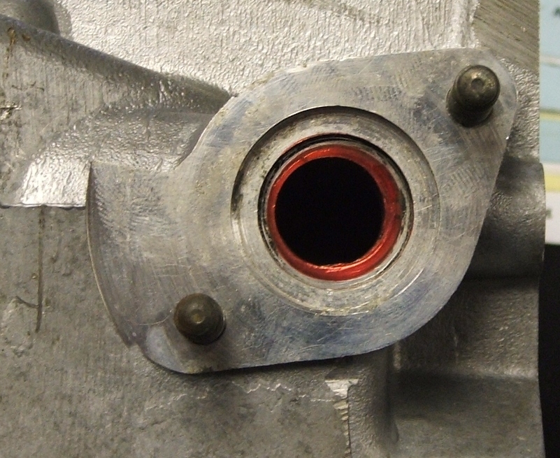 Anyway i decided to illustrate the chanito way to center a port, as you can see i used a permanent marker but machinist die works a lot better, but i figure you guys will have the marker handy, then i just have to find a drill bit that will fit, with the side on the wall and the center of the bit at the narrowest part then just go around so you can mark a circle on the port. 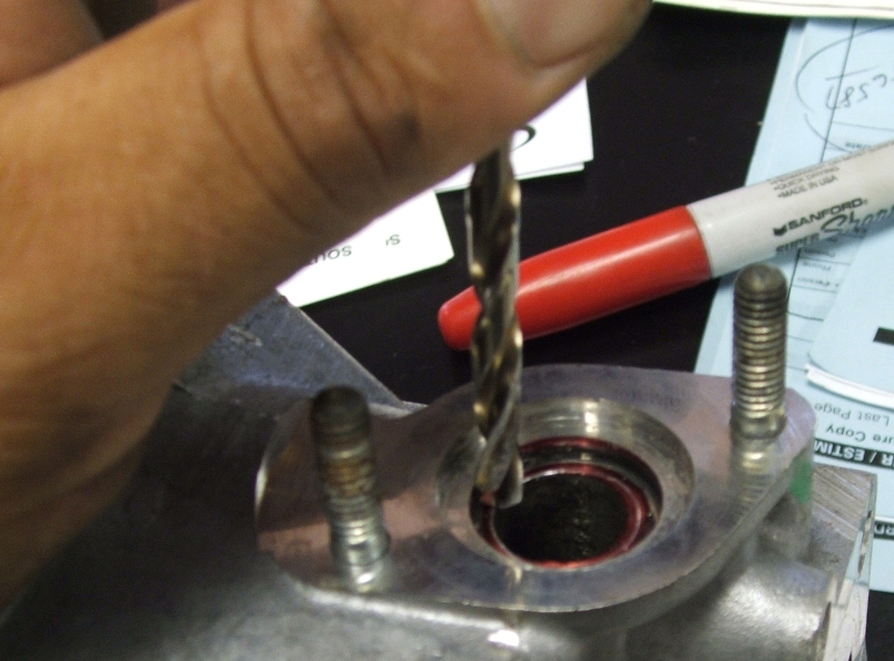 then get your grinder and very carefully grind until the scribed circle is the port, be careful, you do not want that circle any bigger than that, so at the end of the day this is how your ports should look like 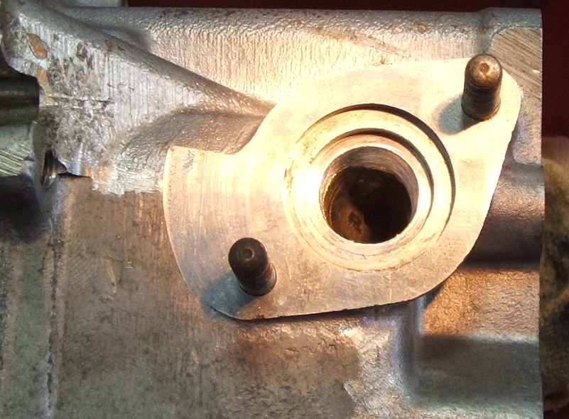 Also grind the vacuum tube off from the intake and you got yourself a nice street ported head 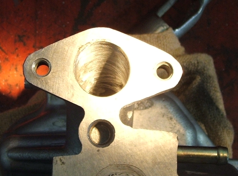 just make sure to clean off any metal shaving, and you can now get yourself a beer and toast to free flow 
|
|
|
|
Post by tedsmini on Jul 10, 2006 20:43:02 GMT -5
Chanito: if there are two compression rings and one multi part oil ring, has anybody mentioned how critical it is to stagger the gaps?  |
|
|
|
Post by chanito on Jul 10, 2006 20:44:40 GMT -5
Chano, is the extrude honing anything like we used to have that was called "vapor honing"? The pix were great, I used to use tin cans and worm drive hose clamps for ring compressors when I was poor and couldn't afford the proper tool. The only things I never scrimped on was anti-seize compound, rubber gloves and lots of the best assembly lube to keep everything clean and lubed. Extrude honing is a process where they force an abrasive gel thru the port at high pressure so this gel sands the inside of the port plus it will grind more any restriction, making the passageway more even. I thought about using the tin and hose clamp method, but since these are forged racing pistons that means the land (where the rings go) is smaller than the skirts (which is coated) so that created a problem as the piston is pushed from the bottom up and it will make it tighter as it goes up, my easiest solution was the spring clamp method  |
|
|
|
Post by chanito on Jul 10, 2006 20:46:45 GMT -5
Chanito: if there are two compression rings and one multi part oil ring, has anybody mentioned how critical it is to stagger the gaps?  ???Is in the manual, but it is worth mentioning the rings should be stagger 120 degrees apart so the gaps do not line up ;D |
|
|
|
Post by Dandy Dan on Jul 11, 2006 8:53:10 GMT -5
That's for all the great info guys ;D
The manual really is essential for a job like this just because it explains everything so well with nice pics and helps you not to forget anything.
Chanito/ZoomZoom: Good 'ring gap' explanations! I understand what this gap is but is there a certain gap width I'm hoping for? Maybe that's in the service manual...
|
|
|
|
Post by chanito on Jul 11, 2006 14:40:02 GMT -5
Probably you are referring to the piston to wall CLEARANCE, which is the room between the piston and the cylinder wall, since the big piston is forged this need to be bigger than the stock, you will need a micrometer to measure the outside of the piston and an inside micrometer for the cyl, the difference is the clearance, that is one of the numbers written on my piston by the machine shop, a good machine shop should take care of that and give you the engine already honed to the right size  |
|
|
|
Post by Dandy Dan on Jul 11, 2006 15:37:56 GMT -5
Chanito, you said that if the ring gap is zero (ie, the C is actually an 0 ) then that's bad and you said we want a bit of a gap so when the rings expand they seal but obviously we wouldn't want like a 1/4" gap so I was just asking how big of a gap is too big? 2mm?
The shop that's doing the work called me today and they got their boring machine working again so my engine is getting bored out today. Unfortunately, they have the honing tools but for some wierd reason they can't do it (they explained it but I was lost, something to do with the shape of the engine) so they are sending it to another place for the honing so my total cost is gonna be a bit more ($99 Cdn). This should for sure be done this week though and I'm getting pumped to start early on Saturday and get everything put together that day. I'll be surprised if I have enough time to rejet it too though.
When is your engine gonna be all back together Chanito? Keep us posted on that and your jetting findings.
My new plan is to not use the Metro gears right away because I'm getting married next month and I'll need to carry the wife around on the Ruckus sometimes so I don't want to be geared that tall and suck up hills with her. She'll be fine with holding 45mph all the time but if it's 50mph on flats and 35mph up hills she'll get frustrated. Assuming the big bore piston provides a decent boost in power the plan is to swap in the Metro gears around November when we buy a car and put the Ruckus away for the winter...we were planning on getting a 1 bedroom apartment but we ended up finding a nice 2 bdrm one for $9/month more so we're planning on getting that and then the 2nd bedroom can be sort of music/Ruckus/Mtn Bike/Computer room.
|
|
|
|
Post by rucktune on Jul 11, 2006 20:38:22 GMT -5
Dandy Dan, my friend, this piston business is too important and exciting to sully with the stress of a MARRIAGE!, for God's sake, I recommend you put the marriage thing on hold till you and Chanito are up and running on your scooters. The eyes of the Ruckus world are upon you!
|
|
|
|
Post by Kami no Chiizu on Jul 11, 2006 21:09:33 GMT -5
|
|